Machine Foundations

Chapter 2. Block Foundation

2.6 Examples

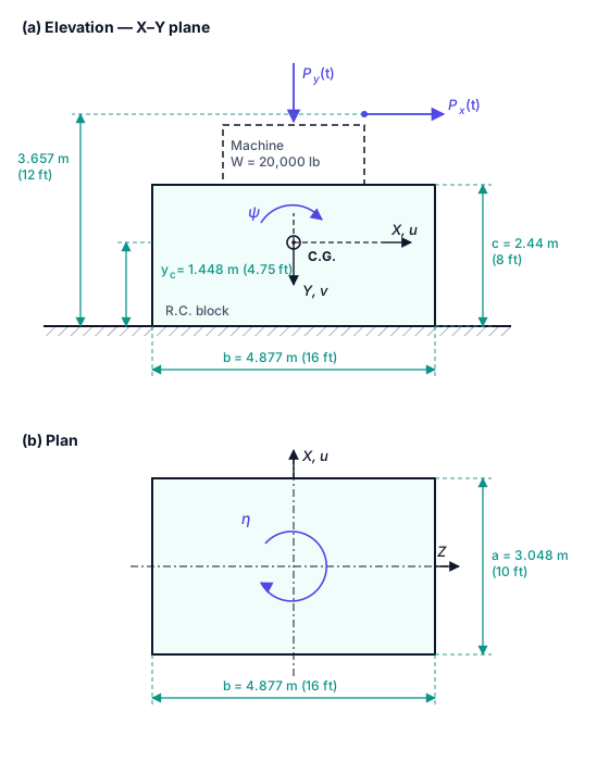
Figure 2.6.1 Machine Foundation of Example 2.6.1

Example 2.6.1

A centrifugal machine is supported on the rigid reinforced concrete block shown in Figure 2.6.1. The block rests directly on the surface of a deep, uniform granular deposit, so that no embedment is available (l=0 l = 0). Using the constant halfspace parameters of the Novak–Beredugo model, calculate the stiffness and damping constants of the foundation for the vertical mode v v, the coupled horizontal–rocking mode uψ u - \psi in the X–Y plane, and the torsional mode η \eta. All constants are to be referred to the centre of gravity of the machine-plus-block system. Then adjust the constants to account for the soil material damping.

Table 2.6.1 Given Data for Example 2.6.1

ItemQuantitySIUS Customary
MachineWeight88.96 kN20,000 lb
MachineHeight of horizontal excitation3.657 m12 ft
FootingReinforced concrete unit weight γc\gamma_c23.57 kN/m3150 lb/ft3
FootingPlan dimension aa (rocking direction)3.048 m10 ft
FootingPlan dimension bb4.877 m16 ft
FootingThickness cc2.44 m8 ft
FootingEmbedment depth ll00
FootingHeight of the system C.G. above the base ycy_c1.448 m4.75 ft
SoilUnit weight γ\gamma15.714 kN/m3100 lb/ft3
SoilMass density ρ\rho1602 kg/m33.105 slug/ft3
SoilShear wave velocity VsV_s150 m/s492.1 ft/s
SoilMaterial damping tanδ=2βm\tan \delta = 2 \beta_m0.100.10
SoilPoisson's ratio ν\nu (granular)0.250.25
SystemTotal mass of machine + block mm9.60 × 104 kg6583 slug

The foundation rests on the surface of a homogeneous halfspace, so the embedment length is l=0l = 0 and the embedment ratio δ=l/R\delta = l / R is also zero. Every side-layer term Si1S_{i1} and Si2S_{i2} therefore drops out of the Novak–Beredugo equations, and only the halfspace parameters Ci1C_{i1} and Ci2\overline{C}_{i2} remain. The constants are calculated for the three vibration modes: the vertical mode, the coupled horizontal–rocking mode in the X–Y plane, and the torsional mode.

Step 1 — Equivalent radii of the rectangular base

The rectangular base is replaced by an equivalent circular disc. The translational radius is obtained from an equal contact area, while each rotational radius is obtained from an equal moment of inertia about the axis of rotation,

Ru=Rv=abπ=3.048×4.877π=14.865πR_u = R_v = \sqrt{\frac{a b}{\pi}} = \sqrt{\frac{3.048 \times 4.877}{\pi}} = \sqrt{\frac{14.865}{\pi}}
Ru=Rv=2.175 m=7.13 ftR_u = R_v = 2.175 \space \text{m} = 7.13 \space \text{ft}
Rψ=ba33π4=4.877×(3.048)33π4=138.119.4254R_{\psi} = \sqrt[4]{\frac{b a^3}{3 \pi}} = \sqrt[4]{\frac{4.877 \times (3.048)^3}{3 \pi}} = \sqrt[4]{\frac{138.11}{9.425}}
Rψ=14.654=1.957 m=6.42 ftR_{\psi} = \sqrt[4]{14.65} = 1.957 \space \text{m} = 6.42 \space \text{ft}
Rη=ab(a2+b2)6π4=14.865×((3.048)2+(4.877)2)6π4R_{\eta} = \sqrt[4]{\frac{a b (a^2 + b^2)}{6 \pi}} = \sqrt[4]{\frac{14.865 \times \big( (3.048)^2 + (4.877)^2 \big)}{6 \pi}}
Rη=14.865×33.0718.854=26.084=2.260 m=7.41 ftR_{\eta} = \sqrt[4]{\frac{14.865 \times 33.07}{18.85}} = \sqrt[4]{26.08} = 2.260 \space \text{m} = 7.41 \space \text{ft}

Note that a=3.048 ma = 3.048 \space \text{m} is the plan dimension measured in the direction of rocking (parallel to the X axis), and that the aspect ratio b/a=1.6<2b/a = 1.6 < 2, so the equivalent-radius idealisation is acceptable.

Step 2 — Soil shear modulus and impedance coefficient

The shear wave velocity is related to the shear modulus of the soil by,

Vs=GρG=ρVs2V_s = \sqrt{\frac{G}{\rho}} \quad \Rightarrow \quad G = \rho V_s^2
G=1602×(150)2=3.6045×10⁷ N/m2=7.528×105 lb/ft2G = 1602 \times (150)^2 = 3.6045 \times 10^{7} \space \text{N/m}^2 = 7.528 \times 10^{5} \space \text{lb/ft}^2

All of the damping constants are proportional to the quantity ρG\sqrt{\rho G}, which is evaluated once and reused throughout,

ρG=1602×3.6045×107=2.403×10⁵ N.s/m3\sqrt{\rho G} = \sqrt{1602 \times 3.6045 \times 10^{7}} = 2.403 \times 10^{5} \space \text{N.s/m}^3

Step 3 — Halfspace parameters

The soil is granular with ν=0.25\nu = 0.25. Reading the halfspace columns of Table 2.4.1 (identical to Table 5.4.1.2 of ACI 351.3R-18) gives the following constant approximations, which are valid for a dimensionless frequency ao<2.0a_o < 2.0,

Cv1=5.2Cv2=5.0C_{v1} = 5.2 \qquad \overline{C}_{v2} = 5.0
Cu1=4.7Cu2=2.8C_{u1} = 4.7 \qquad \overline{C}_{u2} = 2.8
Cψ1=3.3Cψ2=0.5C_{\psi 1} = 3.3 \qquad \overline{C}_{\psi 2} = 0.5
Cη1=4.3Cη2=0.7C_{\eta 1} = 4.3 \qquad \overline{C}_{\eta 2} = 0.7

Step 4 — Vertical mode

The general expressions for an embedded footing are, for the stiffness and the damping constant respectively,

kvv=GRv(Cv1+GsGδSv1)k_{vv} = G R_v \Big( C_{v1} + \frac{G_s}{G} \delta S_{v1} \Big)
cvv=Rv2ρG(Cv2+δρsGsρGSv2)c_{vv} = R_v^2 \sqrt{\rho G} \Big( \overline{C}_{v2} + \delta \sqrt{\frac{\rho_s G_s}{\rho G}} \overline{S}_{v2} \Big)

With δ=0\delta = 0 these reduce to the surface-footing form,

kvv=GRvCv1=3.6045×107×2.175×5.2k_{vv} = G R_v C_{v1} = 3.6045 \times 10^{7} \times 2.175 \times 5.2
kvv=4.077×10⁸ N/m=2.794×107 lb/ftk_{vv} = 4.077 \times 10^{8} \space \text{N/m} = 2.794 \times 10^{7} \space \text{lb/ft}
cvv=Rv2ρG Cv2=(2.175)2×2.403×105×5.0c_{vv} = R_v^2 \sqrt{\rho G} \space \overline{C}_{v2} = (2.175)^2 \times 2.403 \times 10^{5} \times 5.0
cvv=5.685×10⁶ N.s/m=3.896×105 lb.s/ftc_{vv} = 5.685 \times 10^{6} \space \text{N.s/m} = 3.896 \times 10^{5} \space \text{lb.s/ft}

Step 5 — Coupled horizontal and rocking mode

Because the footing has a finite height, a horizontal translation of the base produces a moment about the centre of gravity, and a rotation produces a horizontal force. The motion is therefore coupled and four constants are required: kuuk_{uu}, kψψk_{\psi \psi}, the cross term kuψ=kψuk_{u \psi} = k_{\psi u}, and their damping counterparts. All of them are referred to the centre of gravity, which lies at yc=1.448 my_c = 1.448 \space \text{m} above the base.

Horizontal translation

kuu=GRuCu1=3.6045×107×2.175×4.7k_{uu} = G R_u C_{u1} = 3.6045 \times 10^{7} \times 2.175 \times 4.7
kuu=3.685×10⁸ N/m=2.525×107 lb/ftk_{uu} = 3.685 \times 10^{8} \space \text{N/m} = 2.525 \times 10^{7} \space \text{lb/ft}
cuu=Ru2ρG Cu2=(2.175)2×2.403×105×2.8c_{uu} = R_u^2 \sqrt{\rho G} \space \overline{C}_{u2} = (2.175)^2 \times 2.403 \times 10^{5} \times 2.8
cuu=3.184×10⁶ N.s/m=2.182×105 lb.s/ftc_{uu} = 3.184 \times 10^{6} \space \text{N.s/m} = 2.182 \times 10^{5} \space \text{lb.s/ft}

Rocking

The rocking stiffness about the centre of gravity is the sum of the true rocking resistance of the base and the moment generated by the base shear acting at the lever arm ycy_c,

kψψ=G[Rψ3Cψ1+Ru3(ycRu)2Cu1]k_{\psi \psi} = G \Big[ R_{\psi}^3 C_{\psi 1} + R_u^3 \Big( \frac{y_c}{R_u} \Big)^2 C_{u1} \Big]
kψψ=3.6045×10⁷[(1.957)3×3.3+(2.175)3(1.4482.175)2×4.7]k_{\psi \psi} = 3.6045 \times 10^{7} \Big[ (1.957)^3 \times 3.3 + (2.175)^3 \Big( \frac{1.448}{2.175} \Big)^2 \times 4.7 \Big]
kψψ=3.6045×10⁷[24.71+21.44]=3.6045×107×46.15k_{\psi \psi} = 3.6045 \times 10^{7} \big[ 24.71 + 21.44 \big] = 3.6045 \times 10^{7} \times 46.15
kψψ=1.664×10⁹ N.m/rad=1.227×109 lb.ft/radk_{\psi \psi} = 1.664 \times 10^{9} \space \text{N.m/rad} = 1.227 \times 10^{9} \space \text{lb.ft/rad}
cψψ=ρG[Rψ4Cψ2+Ru4(ycRu)2Cu2]c_{\psi \psi} = \sqrt{\rho G} \Big[ R_{\psi}^4 \overline{C}_{\psi 2} + R_u^4 \Big( \frac{y_c}{R_u} \Big)^2 \overline{C}_{u2} \Big]
cψψ=2.403×10⁵[(1.957)4×0.5+(2.175)4(1.4482.175)2×2.8]c_{\psi \psi} = 2.403 \times 10^{5} \Big[ (1.957)^4 \times 0.5 + (2.175)^4 \Big( \frac{1.448}{2.175} \Big)^2 \times 2.8 \Big]
cψψ=2.403×10⁵[7.33+27.78]=2.403×105×35.11c_{\psi \psi} = 2.403 \times 10^{5} \big[ 7.33 + 27.78 \big] = 2.403 \times 10^{5} \times 35.11
cψψ=8.436×10⁶ N.m.s/rad=6.222×106 lb.ft.s/radc_{\psi \psi} = 8.436 \times 10^{6} \space \text{N.m.s/rad} = 6.222 \times 10^{6} \space \text{lb.ft.s/rad}

Cross (coupling) terms

The cross terms carry a negative sign under the sign convention in which a positive translation uu and a positive rotation ψ\psi are as shown in Figure 2.6.1,

kuψ=kψu=GRu yc Cu1=3.6045×107×2.175×1.448×4.7k_{u \psi} = k_{\psi u} = - G R_u \space y_c \space C_{u1} = - 3.6045 \times 10^{7} \times 2.175 \times 1.448 \times 4.7
kuψ=5.336×10⁸ N/rad=1.200×108 lb/radk_{u \psi} = - 5.336 \times 10^{8} \space \text{N/rad} = - 1.200 \times 10^{8} \space \text{lb/rad}
cuψ=cψu=ρG Ru2 yc Cu2=2.403×105×(2.175)2×1.448×2.8c_{u \psi} = c_{\psi u} = - \sqrt{\rho G} \space R_u^2 \space y_c \space \overline{C}_{u2} = - 2.403 \times 10^{5} \times (2.175)^2 \times 1.448 \times 2.8
cuψ=4.610×10⁶ N.s/rad=1.036×106 lb.s/radc_{u \psi} = - 4.610 \times 10^{6} \space \text{N.s/rad} = - 1.036 \times 10^{6} \space \text{lb.s/rad}

Step 6 — Torsional mode

Torsion is uncoupled from the other degrees of freedom, so a single pair of constants is needed,

kηη=GRη3Cη1=3.6045×107×(2.260)3×4.3k_{\eta \eta} = G R_{\eta}^3 C_{\eta 1} = 3.6045 \times 10^{7} \times (2.260)^3 \times 4.3
kηη=3.6045×107×11.54×4.3=1.789×10⁹ N.m/radk_{\eta \eta} = 3.6045 \times 10^{7} \times 11.54 \times 4.3 = 1.789 \times 10^{9} \space \text{N.m/rad}
kηη=1.319×10⁹ lb.ft/radk_{\eta \eta} = 1.319 \times 10^{9} \space \text{lb.ft/rad}
cηη=Rη4ρG Cη2=(2.260)4×2.403×105×0.7c_{\eta \eta} = R_{\eta}^4 \sqrt{\rho G} \space \overline{C}_{\eta 2} = (2.260)^4 \times 2.403 \times 10^{5} \times 0.7
cηη=4.388×10⁶ N.m.s/rad=3.236×106 lb.ft.s/radc_{\eta \eta} = 4.388 \times 10^{6} \space \text{N.m.s/rad} = 3.236 \times 10^{6} \space \text{lb.ft.s/rad}

Table 2.6.2 Summary of the Stiffness and Damping Constants (material damping neglected)

ModeConstantSIUS Customary
Verticalkvvk_{vv}4.077×1084.077 \times 10^{8} N/m2.794×1072.794 \times 10^{7} lb/ft
Verticalcvvc_{vv}5.685×1065.685 \times 10^{6} N.s/m3.896×1053.896 \times 10^{5} lb.s/ft
Horizontalkuuk_{uu}3.685×1083.685 \times 10^{8} N/m2.525×1072.525 \times 10^{7} lb/ft
Horizontalcuuc_{uu}3.184×1063.184 \times 10^{6} N.s/m2.182×1052.182 \times 10^{5} lb.s/ft
Rockingkψψk_{\psi \psi}1.664×1091.664 \times 10^{9} N.m/rad1.227×1091.227 \times 10^{9} lb.ft/rad
Rockingcψψc_{\psi \psi}8.436×1068.436 \times 10^{6} N.m.s/rad6.222×1066.222 \times 10^{6} lb.ft.s/rad
Crosskuψk_{u \psi}5.336×10⁸-5.336 \times 10^{8} N/rad1.200×108-1.200 \times 10^{8} lb/rad
Crosscuψc_{u \psi}4.610×10⁶-4.610 \times 10^{6} N.s/rad1.036×106-1.036 \times 10^{6} lb.s/rad
Torsionkηηk_{\eta \eta}1.789×1091.789 \times 10^{9} N.m/rad1.319×1091.319 \times 10^{9} lb.ft/rad
Torsioncηηc_{\eta \eta}4.388×1064.388 \times 10^{6} N.m.s/rad3.236×1063.236 \times 10^{6} lb.ft.s/rad

Step 7 — Effect of the soil material damping

The constants above were derived for a perfectly elastic halfspace, so cic_i contains geometric (radiation) damping only. The soil of this example has a hysteretic material damping tanδ=2βm=0.1\tan \delta = 2 \beta_m = 0.1, hence βm=0.05\beta_m = 0.05. Multiplying the elastic impedance by the complex factor (1+2iβm)(1 + 2 i \beta_m) gives the adjusted impedance,

ki(adj)=(ki+iωci)(1+2iβm)=(ki2βmωci)+iω(ci+2βmkiω)k_i^*(adj) = (k_i + i \omega c_i)(1 + 2 i \beta_m) = \big( k_i - 2 \beta_m \omega c_i \big) + i \omega \Big( c_i + \frac{2 \beta_m k_i}{\omega} \Big)

Separating the real and the imaginary parts,

ki(adj)=ki2βmωcik_i(adj) = k_i - 2 \beta_m \omega c_i
ci(adj)=ci+2βmkiωc_i(adj) = c_i + \frac{2 \beta_m k_i}{\omega}

These expressions are frequency dependent, so a value of ω\omega has to be selected. If the footing is checked at a known operating speed, that speed is substituted directly. If complete response curves are required, it is better to evaluate the adjustment at the natural frequency of the mode being examined. For the vertical mode of this footing,

ωv=kvvm=4.077×1089.60×104=65.2 rad/s  (10.4 Hz)\omega_v = \sqrt{\frac{k_{vv}}{m}} = \sqrt{\frac{4.077 \times 10^{8}}{9.60 \times 10^{4}}} = 65.2 \space \text{rad/s} \space \space (10.4 \space \text{Hz})

The corresponding dimensionless frequency confirms that the constant parameters of Step 3 were read in their valid range,

aov=ωvRvVs=65.2×2.175150=0.945<2.0OKa_{ov} = \frac{\omega_v R_v}{V_s} = \frac{65.2 \times 2.175}{150} = 0.945 < 2.0 \quad \text{OK}

Substituting into the adjustment equations,

kvv(adj)=4.077×1082(0.05)(65.2)(5.685×10⁶)k_{vv}(adj) = 4.077 \times 10^{8} - 2 (0.05)(65.2)(5.685 \times 10^{6})
kvv(adj)=4.077×1080.371×108=3.706×10⁸ N/mk_{vv}(adj) = 4.077 \times 10^{8} - 0.371 \times 10^{8} = 3.706 \times 10^{8} \space \text{N/m}
cvv(adj)=5.685×10⁶+2(0.05)(4.077×10⁸)65.2c_{vv}(adj) = 5.685 \times 10^{6} + \frac{2 (0.05)(4.077 \times 10^{8})}{65.2}
cvv(adj)=5.685×10⁶+0.626×106=6.311×10⁶ N.s/mc_{vv}(adj) = 5.685 \times 10^{6} + 0.626 \times 10^{6} = 6.311 \times 10^{6} \space \text{N.s/m}

The material damping reduces the vertical stiffness by about 9 % and raises the vertical damping constant by about 11 %. The same procedure is applied to the remaining modes once their natural frequencies are known.

Step 8 — Equivalent damping ratio and code limits

It is often more convenient to express the result as a damping ratio. For the vertical mode, using the elastic (geometric) constants,

βv=cvv2kvv m=5.685×1062(4.077×10⁸)(9.60×10⁴)=0.45\beta_v = \frac{c_{vv}}{2 \sqrt{k_{vv} \space m}} = \frac{5.685 \times 10^{6}}{2 \sqrt{(4.077 \times 10^{8})(9.60 \times 10^{4})}} = 0.45

A geometric damping ratio of 45 % is very high. Both experiments and field measurements show that large foundations vibrating at small amplitudes develop less damping than the halfspace theory predicts, because reflected waves return energy to the footing. ACI 351.3R-18 (section 5.4.2) therefore recommends capping the calculated value, for example the EPRI limit of 50 % for vertical motion, the DIN 4024-2 limit of 25 % for rigid block foundations, or the 50 % reduction of the analytical value suggested by Novak.

Observations

Only the halfspace parameters survive when l=0l = 0. Embedding the same block would add the side-layer terms Si1S_{i1} and Si2S_{i2}, which increase every stiffness and, more importantly, increase the damping substantially. This is why guideline No. 8 for trial sizing recommends embedding the block whenever it is practical.

The rocking stiffness about the centre of gravity is dominated by neither term alone. The true rocking resistance of the base contributes 24.71/46.15=54%24.71 / 46.15 = 54 \% and the base shear acting at the lever arm ycy_c contributes the remaining 46 %. Lowering the centre of gravity, by making the block thicker and the machine mount lower, reduces the coupling.

The cross terms kuψk_{u \psi} and cuψc_{u \psi} are negative and are not small compared with the diagonal terms. They cannot be ignored: the horizontal and rocking modes must be solved as a two degree of freedom coupled system, which is carried out in Chapter 4.

Material damping acts in both directions. It removes stiffness in proportion to ωci\omega c_i and adds damping in proportion to ki/ωk_i / \omega, so its relative importance grows as the operating frequency falls.
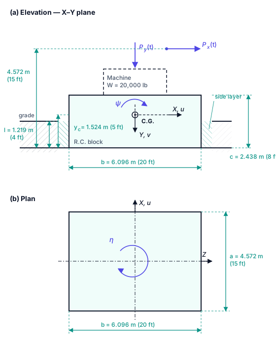
Figure 2.6.2 Embedded Machine Foundation of Example 2.6.2

Example 2.6.2

The block of Example 2.6.1 is enlarged and is now cast against undisturbed native soil so that half of its thickness is below grade, giving an embedment depth l=1.219 m (4 ft) l = 1.219 \space \text{m} \space (4 \space \text{ft}). The soil is heavier and has a higher Poisson's ratio. Calculate the stiffness and damping constants for the vertical mode v v, the coupled horizontal–rocking mode uψ u - \psi in the X–Y plane, and the torsional mode η \eta, all referred to the centre of gravity of the machine-plus-block system. Separate the base contribution from the side-layer contribution in every mode, and comment on what the embedment buys.

Table 2.6.3 Given Data for Example 2.6.2

ItemQuantitySIUS Customary
MachineWeight88.96 kN20,000 lb
MachineHeight of horizontal excitation4.572 m15 ft
FootingReinforced concrete unit weight γc\gamma_c23.57 kN/m3150 lb/ft3
FootingPlan dimension aa (rocking direction)4.572 m15 ft
FootingPlan dimension bb6.096 m20 ft
FootingThickness cc2.438 m8 ft
FootingEmbedment depth ll1.219 m4 ft
FootingHeight of the system C.G. above the base ycy_c1.524 m5 ft
SoilUnit weight γ\gamma18.85 kN/m3120 lb/ft3
SoilMass density ρ\rho1922 kg/m33.727 slug/ft3
SoilShear wave velocity VsV_s150 m/s492.1 ft/s
SoilMaterial damping tanδ=2βm\tan \delta = 2 \beta_m0.100.10
SoilPoisson's ratio ν\nu0.330.33
Side layerUndisturbed native soil, Gs=GG_s = G, ρs=ρ\rho_s = \rho
SystemTotal mass of machine + block mm1.724 × 105 kg11,800 slug

The embedment length is no longer zero, so every constant now carries two contributions: a base term generated by the soil reactions under the footing, governed by the halfspace parameters Ci1C_{i1} and Ci2\overline{C}_{i2}, and a side-layer term generated by the soil reacting against the buried faces of the block, governed by the parameters Si1S_{i1} and Si2\overline{S}_{i2}. Both are calculated below and kept separate so that the value of the embedment can be seen directly.

Choice of soil class. Table 2.4.1 tabulates the parameters for only two broad classes: granular, for which ν=0.25\nu = 0.25 is presumed, and cohesive, for which ν=0.4\nu = 0.4 is presumed. The value ν=0.33\nu = 0.33 given here falls between the two. This example adopts the cohesive column, which is the appropriate class for a soil able to stand against the buried faces of the block and supply the side-layer reactions. The choice is not cosmetic: reading the granular column instead would lower kvvk_{vv} by about 27 % and kψψk_{\psi \psi} by about 16 %. Where ν\nu is known with confidence, the rigorous route is the Veletsos–Verbic closed form of section 2.4, whose coefficients are tabulated at exactly ν=1/3\nu = 1/3; it is implemented in the calculator of section 2.5.

Step 1 — Equivalent radii of the rectangular base

Ru=Rv=abπ=4.572×6.096π=27.871π=2.979 m=9.77 ftR_u = R_v = \sqrt{\frac{a b}{\pi}} = \sqrt{\frac{4.572 \times 6.096}{\pi}} = \sqrt{\frac{27.871}{\pi}} = 2.979 \space \text{m} = 9.77 \space \text{ft}
Rψ=ba33π4=6.096×(4.572)33π4=582.69.4254R_{\psi} = \sqrt[4]{\frac{b a^3}{3 \pi}} = \sqrt[4]{\frac{6.096 \times (4.572)^3}{3 \pi}} = \sqrt[4]{\frac{582.6}{9.425}}
Rψ=61.814=2.804 m=9.20 ftR_{\psi} = \sqrt[4]{61.81} = 2.804 \space \text{m} = 9.20 \space \text{ft}
Rη=ab(a2+b2)6π4=27.871×((4.572)2+(6.096)2)6π4R_{\eta} = \sqrt[4]{\frac{a b (a^2 + b^2)}{6 \pi}} = \sqrt[4]{\frac{27.871 \times \big( (4.572)^2 + (6.096)^2 \big)}{6 \pi}}
Rη=27.871×58.0618.854=85.854=3.044 m=9.99 ftR_{\eta} = \sqrt[4]{\frac{27.871 \times 58.06}{18.85}} = \sqrt[4]{85.85} = 3.044 \space \text{m} = 9.99 \space \text{ft}

The aspect ratio is b/a=1.33<2b/a = 1.33 < 2, so the equivalent-radius idealisation remains acceptable.

Step 2 — Soil properties

The mass density follows from the given unit weight,

ρ=γg=18 8509.81=1922 kg/m3=3.727 slug/ft3\rho = \frac{\gamma}{g} = \frac{18 \space 850}{9.81} = 1922 \space \text{kg/m}^3 = 3.727 \space \text{slug/ft}^3
G=ρVs2=1922×(150)2=4.323×10⁷ N/m2=9.030×105 lb/ft2G = \rho V_s^2 = 1922 \times (150)^2 = 4.323 \times 10^{7} \space \text{N/m}^2 = 9.030 \times 10^{5} \space \text{lb/ft}^2
ρG=1922×4.323×107=2.882×10⁵ N.s/m3\sqrt{\rho G} = \sqrt{1922 \times 4.323 \times 10^{7}} = 2.882 \times 10^{5} \space \text{N.s/m}^3

The block is cast against undisturbed native soil, so the side layer has the same properties as the base soil,

GsG=1andρsGsρG=1\frac{G_s}{G} = 1 \qquad \text{and} \qquad \sqrt{\frac{\rho_s G_s}{\rho G}} = 1

Step 3 — Embedment ratios and side-layer parameters

The embedment ratio is referred to the equivalent radius of the mode being considered, δi=l/Ri\delta_i = l / R_i,

δv=δu=1.2192.979=0.409δψ=1.2192.804=0.435δη=1.2193.044=0.401\delta_v = \delta_u = \frac{1.219}{2.979} = 0.409 \qquad \delta_{\psi} = \frac{1.219}{2.804} = 0.435 \qquad \delta_{\eta} = \frac{1.219}{3.044} = 0.401

Reading the cohesive rows of Table 2.4.1 for both the halfspace and the side layer,

Cv1=7.5Cv2=6.8Sv1=2.7Sv2=6.7C_{v1} = 7.5 \quad \overline{C}_{v2} = 6.8 \quad S_{v1} = 2.7 \quad \overline{S}_{v2} = 6.7
Cu1=5.1Cu2=3.2Su1=4.1Su2=10.6C_{u1} = 5.1 \quad \overline{C}_{u2} = 3.2 \quad S_{u1} = 4.1 \quad \overline{S}_{u2} = 10.6
Cψ1=4.3Cψ2=0.7Sψ1=2.5Sψ2=1.8C_{\psi 1} = 4.3 \quad \overline{C}_{\psi 2} = 0.7 \quad S_{\psi 1} = 2.5 \quad \overline{S}_{\psi 2} = 1.8
Cη1=4.3Cη2=0.7Sη1=10.2Sη2=5.4C_{\eta 1} = 4.3 \quad \overline{C}_{\eta 2} = 0.7 \quad S_{\eta 1} = 10.2 \quad \overline{S}_{\eta 2} = 5.4

Step 4 — Vertical mode

kvv=GRv(Cv1+GsGδvSv1)=GRvCv1+Gs l Sv1k_{vv} = G R_v \Big( C_{v1} + \frac{G_s}{G} \delta_v S_{v1} \Big) = G R_v C_{v1} + G_s \space l \space S_{v1}
kvv=4.323×107×2.979×7.5+4.323×107×1.219×2.7k_{vv} = 4.323 \times 10^{7} \times 2.979 \times 7.5 + 4.323 \times 10^{7} \times 1.219 \times 2.7
kvv=9.658×10⁸+1.423×108=1.108×10⁹ N/m=7.593×107 lb/ftk_{vv} = 9.658 \times 10^{8} + 1.423 \times 10^{8} = 1.108 \times 10^{9} \space \text{N/m} = 7.593 \times 10^{7} \space \text{lb/ft}
cvv=Rv2ρG(Cv2+δvρsGsρGSv2)=ρGRv2Cv2+ρsGs Rv l Sv2c_{vv} = R_v^2 \sqrt{\rho G} \Big( \overline{C}_{v2} + \delta_v \sqrt{\frac{\rho_s G_s}{\rho G}} \overline{S}_{v2} \Big) = \sqrt{\rho G} R_v^2 \overline{C}_{v2} + \sqrt{\rho_s G_s} \space R_v \space l \space \overline{S}_{v2}
cvv=2.882×105×(2.979)2×6.8+2.882×105×2.979×1.219×6.7c_{vv} = 2.882 \times 10^{5} \times (2.979)^2 \times 6.8 + 2.882 \times 10^{5} \times 2.979 \times 1.219 \times 6.7
cvv=1.739×10⁷+7.013×106=2.440×10⁷ N.s/m=1.672×106 lb.s/ftc_{vv} = 1.739 \times 10^{7} + 7.013 \times 10^{6} = 2.440 \times 10^{7} \space \text{N.s/m} = 1.672 \times 10^{6} \space \text{lb.s/ft}

Step 5 — Coupled horizontal and rocking mode

Horizontal translation

kuu=GRuCu1+Gs l Su1=4.323×107×2.979×5.1+4.323×107×1.219×4.1k_{uu} = G R_u C_{u1} + G_s \space l \space S_{u1} = 4.323 \times 10^{7} \times 2.979 \times 5.1 + 4.323 \times 10^{7} \times 1.219 \times 4.1
kuu=6.568×10⁸+2.161×108=8.729×10⁸ N/m=5.981×107 lb/ftk_{uu} = 6.568 \times 10^{8} + 2.161 \times 10^{8} = 8.729 \times 10^{8} \space \text{N/m} = 5.981 \times 10^{7} \space \text{lb/ft}
cuu=ρGRu2Cu2+ρsGs Ru l Su2c_{uu} = \sqrt{\rho G} R_u^2 \overline{C}_{u2} + \sqrt{\rho_s G_s} \space R_u \space l \space \overline{S}_{u2}
cuu=2.882×105×8.872×3.2+2.882×105×2.979×1.219×10.6c_{uu} = 2.882 \times 10^{5} \times 8.872 \times 3.2 + 2.882 \times 10^{5} \times 2.979 \times 1.219 \times 10.6
cuu=8.183×10⁶+1.110×107=1.928×10⁷ N.s/m=1.321×106 lb.s/ftc_{uu} = 8.183 \times 10^{6} + 1.110 \times 10^{7} = 1.928 \times 10^{7} \space \text{N.s/m} = 1.321 \times 10^{6} \space \text{lb.s/ft}

Rocking

The complete expression for the rocking stiffness about the centre of gravity is,

kψψ=GR3[Cψ1+(ycR)2Cu1+GsGδSψ1+GsGδ(δ23+yc2R2δycR)Su1]k_{\psi \psi} = G R^3 \Big[ C_{\psi 1} + \Big( \frac{y_c}{R} \Big)^2 C_{u1} + \frac{G_s}{G} \delta S_{\psi 1} + \frac{G_s}{G} \delta \Big( \frac{\delta^2}{3} + \frac{y_c^2}{R^2} - \delta \frac{y_c}{R} \Big) S_{u1} \Big]

Substituting δ=l/R\delta = l / R and expanding, each term takes the equivalent radius that belongs to it,

kψψ=G[Rψ3Cψ1+Ru yc2 Cu1]+Gs[Rψ2 l Sψ1+Il Su1]k_{\psi \psi} = G \big[ R_{\psi}^3 C_{\psi 1} + R_u \space y_c^2 \space C_{u1} \big] + G_s \big[ R_{\psi}^2 \space l \space S_{\psi 1} + I_l \space S_{u1} \big]

where IlI_l is the second moment of the buried face about the centre of gravity, obtained from 0l(ycy)2dy\int_0^{l} (y_c - y)^2 dy,

Il=yc2 lyc l2+l33=(1.524)2(1.219)(1.524)(1.219)2+(1.219)33I_l = y_c^2 \space l - y_c \space l^2 + \frac{l^3}{3} = (1.524)^2 (1.219) - (1.524)(1.219)^2 + \frac{(1.219)^3}{3}
Il=2.8312.265+0.604=1.170 m3I_l = 2.831 - 2.265 + 0.604 = 1.170 \space \text{m}^3

The base contribution is,

4.323×10⁷[(2.804)3×4.3+2.979×(1.524)2×5.1]4.323 \times 10^{7} \big[ (2.804)^3 \times 4.3 + 2.979 \times (1.524)^2 \times 5.1 \big]
=4.323×10⁷[94.79+35.28]=5.624×10⁹ N.m/rad= 4.323 \times 10^{7} \big[ 94.79 + 35.28 \big] = 5.624 \times 10^{9} \space \text{N.m/rad}

and the side-layer contribution is,

4.323×10⁷[(2.804)2×1.219×2.5+1.170×4.1]4.323 \times 10^{7} \big[ (2.804)^2 \times 1.219 \times 2.5 + 1.170 \times 4.1 \big]
=4.323×10⁷[23.96+4.80]=1.243×10⁹ N.m/rad= 4.323 \times 10^{7} \big[ 23.96 + 4.80 \big] = 1.243 \times 10^{9} \space \text{N.m/rad}
kψψ=5.624×10⁹+1.243×109=6.867×10⁹ N.m/rad=5.065×109 lb.ft/radk_{\psi \psi} = 5.624 \times 10^{9} + 1.243 \times 10^{9} = 6.867 \times 10^{9} \space \text{N.m/rad} = 5.065 \times 10^{9} \space \text{lb.ft/rad}

The rocking damping constant follows the same pattern,

cψψ=ρG[Rψ4Cψ2+Ru2 yc2 Cu2]+ρsGs[Rψ3 l Sψ2+Il Su2]c_{\psi \psi} = \sqrt{\rho G} \big[ R_{\psi}^4 \overline{C}_{\psi 2} + R_u^2 \space y_c^2 \space \overline{C}_{u2} \big] + \sqrt{\rho_s G_s} \big[ R_{\psi}^3 \space l \space \overline{S}_{\psi 2} + I_l \space \overline{S}_{u2} \big]
=2.882×10⁵[61.81×0.7+8.872×2.323×3.2]= 2.882 \times 10^{5} \big[ 61.81 \times 0.7 + 8.872 \times 2.323 \times 3.2 \big]
+ 2.882×10⁵[22.05×1.219×1.8+1.170×10.6]+ \space 2.882 \times 10^{5} \big[ 22.05 \times 1.219 \times 1.8 + 1.170 \times 10.6 \big]
=2.882×10⁵[43.27+65.94]+2.882×10⁵[48.37+12.41]= 2.882 \times 10^{5} \big[ 43.27 + 65.94 \big] + 2.882 \times 10^{5} \big[ 48.37 + 12.41 \big]
cψψ=3.148×10⁷+1.752×107=4.900×10⁷ N.m.s/rad=3.614×107 lb.ft.s/radc_{\psi \psi} = 3.148 \times 10^{7} + 1.752 \times 10^{7} = 4.900 \times 10^{7} \space \text{N.m.s/rad} = 3.614 \times 10^{7} \space \text{lb.ft.s/rad}

Cross (coupling) terms

The side-layer reaction acts over the depth ll, so its resultant sits at mid-depth and the lever arm about the centre of gravity is (ycl/2)(y_c - l/2),

kuψ=[GRu yc Cu1+Gs l (ycl2)Su1]k_{u \psi} = - \Big[ G R_u \space y_c \space C_{u1} + G_s \space l \space \Big( y_c - \frac{l}{2} \Big) S_{u1} \Big]
=[4.323×107×2.979×1.524×5.1+4.323×107×1.219×0.914×4.1]= - \big[ 4.323 \times 10^{7} \times 2.979 \times 1.524 \times 5.1 + 4.323 \times 10^{7} \times 1.219 \times 0.914 \times 4.1 \big]
kuψ=[1.001×10⁹+1.976×10⁸]=1.199×10⁹ N/rad=2.694×108 lb/radk_{u \psi} = - \big[ 1.001 \times 10^{9} + 1.976 \times 10^{8} \big] = - 1.199 \times 10^{9} \space \text{N/rad} = - 2.694 \times 10^{8} \space \text{lb/rad}
cuψ=[ρGRu2 yc Cu2+ρsGs Ru l (ycl2)Su2]c_{u \psi} = - \Big[ \sqrt{\rho G} R_u^2 \space y_c \space \overline{C}_{u2} + \sqrt{\rho_s G_s} \space R_u \space l \space \Big( y_c - \frac{l}{2} \Big) \overline{S}_{u2} \Big]
=[2.882×105×8.872×1.524×3.2+2.882×105×2.979×1.219×0.914×10.6]= - \big[ 2.882 \times 10^{5} \times 8.872 \times 1.524 \times 3.2 + 2.882 \times 10^{5} \times 2.979 \times 1.219 \times 0.914 \times 10.6 \big]
cuψ=[1.247×10⁷+1.014×10⁷]=2.262×10⁷ N.s/rad=5.084×106 lb.s/radc_{u \psi} = - \big[ 1.247 \times 10^{7} + 1.014 \times 10^{7} \big] = - 2.262 \times 10^{7} \space \text{N.s/rad} = - 5.084 \times 10^{6} \space \text{lb.s/rad}

Step 6 — Torsional mode

kηη=GRη3(Cη1+GsGδηSη1)=GRη3Cη1+GsRη2 l Sη1k_{\eta \eta} = G R_{\eta}^3 \Big( C_{\eta 1} + \frac{G_s}{G} \delta_{\eta} S_{\eta 1} \Big) = G R_{\eta}^3 C_{\eta 1} + G_s R_{\eta}^2 \space l \space S_{\eta 1}
kηη=4.323×107×28.20×4.3+4.323×107×9.266×1.219×10.2k_{\eta \eta} = 4.323 \times 10^{7} \times 28.20 \times 4.3 + 4.323 \times 10^{7} \times 9.266 \times 1.219 \times 10.2
kηη=5.243×10⁹+4.982×109=1.022×10¹⁰ N.m/rad=7.542×109 lb.ft/radk_{\eta \eta} = 5.243 \times 10^{9} + 4.982 \times 10^{9} = 1.022 \times 10^{10} \space \text{N.m/rad} = 7.542 \times 10^{9} \space \text{lb.ft/rad}
cηη=ρGRη4Cη2+ρsGsRη3 l Sη2c_{\eta \eta} = \sqrt{\rho G} R_{\eta}^4 \overline{C}_{\eta 2} + \sqrt{\rho_s G_s} R_{\eta}^3 \space l \space \overline{S}_{\eta 2}
cηη=2.882×105×85.85×0.7+2.882×105×28.20×1.219×5.4c_{\eta \eta} = 2.882 \times 10^{5} \times 85.85 \times 0.7 + 2.882 \times 10^{5} \times 28.20 \times 1.219 \times 5.4
cηη=1.732×10⁷+5.352×107=7.084×10⁷ N.m.s/rad=5.225×107 lb.ft.s/radc_{\eta \eta} = 1.732 \times 10^{7} + 5.352 \times 10^{7} = 7.084 \times 10^{7} \space \text{N.m.s/rad} = 5.225 \times 10^{7} \space \text{lb.ft.s/rad}

Table 2.6.4 Summary of the Stiffness and Damping Constants (material damping neglected)

ModeConstantSIUS CustomarySide layer share
Verticalkvvk_{vv}1.108×1091.108 \times 10^{9} N/m7.593×1077.593 \times 10^{7} lb/ft13 %
Verticalcvvc_{vv}2.440×1072.440 \times 10^{7} N.s/m1.672×1061.672 \times 10^{6} lb.s/ft29 %
Horizontalkuuk_{uu}8.729×1088.729 \times 10^{8} N/m5.981×1075.981 \times 10^{7} lb/ft25 %
Horizontalcuuc_{uu}1.928×1071.928 \times 10^{7} N.s/m1.321×1061.321 \times 10^{6} lb.s/ft58 %
Rockingkψψk_{\psi \psi}6.867×1096.867 \times 10^{9} N.m/rad5.065×1095.065 \times 10^{9} lb.ft/rad18 %
Rockingcψψc_{\psi \psi}4.900×1074.900 \times 10^{7} N.m.s/rad3.614×1073.614 \times 10^{7} lb.ft.s/rad36 %
Crosskuψk_{u \psi}1.199×10⁹-1.199 \times 10^{9} N/rad2.694×108-2.694 \times 10^{8} lb/rad16 %
Crosscuψc_{u \psi}2.262×10⁷-2.262 \times 10^{7} N.s/rad5.084×106-5.084 \times 10^{6} lb.s/rad45 %
Torsionkηηk_{\eta \eta}1.022×10101.022 \times 10^{10} N.m/rad7.542×1097.542 \times 10^{9} lb.ft/rad49 %
Torsioncηηc_{\eta \eta}7.084×1077.084 \times 10^{7} N.m.s/rad5.225×1075.225 \times 10^{7} lb.ft.s/rad76 %

Step 7 — Effect of the soil material damping

The material damping is unchanged at tanδ=2βm=0.1\tan \delta = 2 \beta_m = 0.1, so βm=0.05\beta_m = 0.05, and the adjustment of ACI 351.3R-18 Eq. (5.4.4b) and (5.4.4c) applies as before. Evaluating at the vertical natural frequency,

ωv=kvvm=1.108×1091.724×105=80.2 rad/s  (12.8 Hz)\omega_v = \sqrt{\frac{k_{vv}}{m}} = \sqrt{\frac{1.108 \times 10^{9}}{1.724 \times 10^{5}}} = 80.2 \space \text{rad/s} \space \space (12.8 \space \text{Hz})
kvv(adj)=kvv2βmωcvv=1.108×1092(0.05)(80.2)(2.440×10⁷)k_{vv}(adj) = k_{vv} - 2 \beta_m \omega c_{vv} = 1.108 \times 10^{9} - 2 (0.05)(80.2)(2.440 \times 10^{7})
kvv(adj)=1.108×1091.957×108=9.12×10⁸ N/mk_{vv}(adj) = 1.108 \times 10^{9} - 1.957 \times 10^{8} = 9.12 \times 10^{8} \space \text{N/m}
cvv(adj)=cvv+2βmkvvω=2.440×10⁷+2(0.05)(1.108×10⁹)80.2c_{vv}(adj) = c_{vv} + \frac{2 \beta_m k_{vv}}{\omega} = 2.440 \times 10^{7} + \frac{2 (0.05)(1.108 \times 10^{9})}{80.2}
cvv(adj)=2.440×10⁷+1.382×106=2.578×10⁷ N.s/mc_{vv}(adj) = 2.440 \times 10^{7} + 1.382 \times 10^{6} = 2.578 \times 10^{7} \space \text{N.s/m}

The dimensionless frequency should now be checked against the range over which the constant parameters were tabulated,

aov=ωvRvVs=80.2×2.979150=1.59a_{ov} = \frac{\omega_v R_v}{V_s} = \frac{80.2 \times 2.979}{150} = 1.59

The halfspace parameters Ci1C_{i1} and Ci2\overline{C}_{i2} are valid for ao<2.0a_o < 2.0, so they are still in range. The side-layer parameters Si1S_{i1} and Si2\overline{S}_{i2}, however, are tabulated only for 0.5<ao<1.50.5 < a_o < 1.5, and aov=1.59a_{ov} = 1.59 has just passed that limit. Since the side layer supplies 29 % of the vertical damping and 76 % of the torsional damping in this footing, the constant-parameter approximation is being asked to do more work than it comfortably can. For a foundation of this size, the frequency-dependent expressions of section 2.4 and the calculator of section 2.5 should be used to confirm the result.

Step 8 — Equivalent damping ratio and code limits

βv=cvv2kvv m=2.440×1072(1.108×10⁹)(1.724×10⁵)=2.440×1072(1.382×10⁷)=0.88\beta_v = \frac{c_{vv}}{2 \sqrt{k_{vv} \space m}} = \frac{2.440 \times 10^{7}}{2 \sqrt{(1.108 \times 10^{9})(1.724 \times 10^{5})}} = \frac{2.440 \times 10^{7}}{2 (1.382 \times 10^{7})} = 0.88

A geometric damping ratio of 88 % is far beyond anything that should be carried into a response calculation. It is roughly double the 45 % obtained for the surface footing of Example 2.6.1, the increase coming partly from the embedment and partly from the larger base area. Either way the result must be capped: ACI 351.3R-18 (section 5.4.2) cites the EPRI limit of 50 % for vertical motion and the DIN 4024-2 limit of 25 % for rigid block foundations. Taking the DIN limit,

βv (design)=0.25cvv (design)=2(0.25)kvv m=6.91×10⁶ N.s/m\beta_{v} \space \text{(design)} = 0.25 \quad \Rightarrow \quad c_{vv} \space \text{(design)} = 2 (0.25) \sqrt{k_{vv} \space m} = 6.91 \times 10^{6} \space \text{N.s/m}

which is less than one third of the analytical value. This is the single most important practical lesson of the embedded case: the theory predicts damping generously, and the code limit, not the halfspace formula, usually governs the design.

Observations

Embedding the block over only half of its thickness adds 13 % to the vertical stiffness but 29 % to the vertical damping, and 25 % to the horizontal stiffness but 58 % to the horizontal damping. Embedment buys damping far more efficiently than it buys stiffness. This is exactly why the trial-sizing guidelines recommend embedding the block whenever site conditions allow.

Torsion benefits the most. The side layer contributes 49 % of kηηk_{\eta \eta} and 76 % of cηηc_{\eta \eta}, because the side reactions act at the full lever arm RηR_{\eta} from the axis of twist while the base reactions are spread over the contact area.

The rocking stiffness rose from 1.664×1091.664 \times 10^{9} in Example 2.6.1 to 6.867×1096.867 \times 10^{9} N.m/rad, a factor of about 4.1. Most of that comes from the larger plan dimension, since Rψ3R_{\psi}^3 scales roughly with a9/4a^{9/4}, and only 18 % comes from the embedment.

A practical caution: the side-layer terms assume full, permanent contact between the buried faces and the soil. Backfill that shrinks away from the block, or a gap opened by the vibration itself, removes that contribution entirely. Where the contact cannot be relied on, the safe check is to verify the foundation twice, once with the embedment and once as a surface footing.